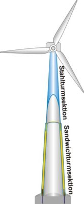
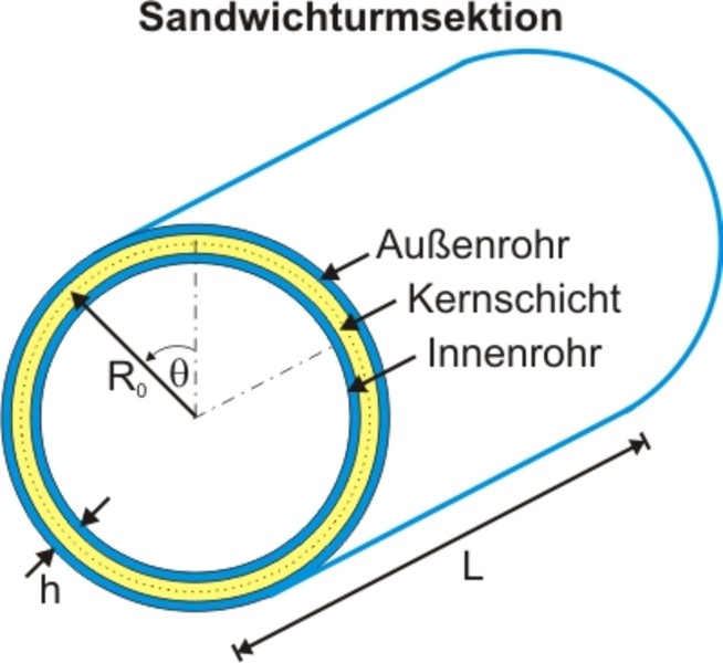
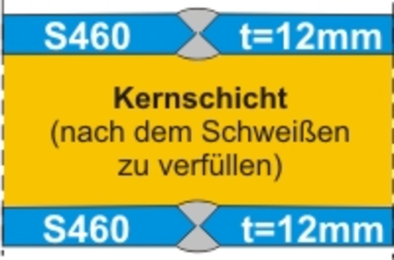
A sandwich tower section basically consists of a steel inner and outer tubes, which are stiffened entire surface by an intervening composite. As composites can pumpable elastomers, epoxy resins and grouts are used, which are filled in ascending order from the base of the tower in the annular gap. In addition to the stiffness and compressive strength of the composite filling materials whose strength is of vital importance for the structural behavior of the sandwich cross-section.

Sandwich tower
A tower as sandwich construction
The performance and size of wind energy plants has increased in recent years more and more. Inevitably, it also increases the demands on the tower structures that were previously used as steel pipe, pre-stressed concrete or lattice tower for execution. Alternatively, a sandwich tower was developed, with which the shell stability and load capacity can be increased. This leads to greater tower heights than with the conventional steel construction can be achieved, while simultaneously increasing the energy yield for the same turbine disproportionately.


Supporting structure in sandwich construction
The principle of a sandwich tower


Sustainability
For the new sandwich tower sections, the cross-section capacities for axial and bending stresses were determined. The elastic moment resistance increases by 30% compared to a steel tower section with the same steel used because the filling material in the annular gap involved in the load transfer on the pressure side bending. The shell stability could be increased to the extent that the yield strength of the inner and outer tube are fully exploited correspondingly large thickness and stiffness of the filler materials. Thus, in principle, the use of higher strength steels for towers of wind turbines feasible.
Mass balance
The development of the sandwich tower made it possible by the combination of high-strength steel and composite materials to reduce the total tonnage with a simultaneous increase in bearing capacity. For example, the steel tonnage to be reduced by 50% compared to a version with a S235 by using a S460. As compared to a steel tower section or savings in weight are possible in spite of the additional filling material.
Damping behavior
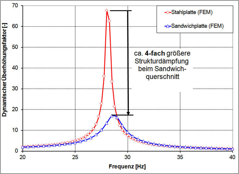
The damping behaviour of a sandwich section was investigated by means of forced harmonic oscillations on cantilever beams with constant mass occupancy and a point mass at the free end. Numerical simulations were used to compare the damping behaviour of a sandwich panel and a steel panel. Based on the resonance spectrum (see diagram), it can be seen that the structural damping of the sandwich cross section is about 4 times higher than for the steel cross section. Although the results are not directly proportional to the pipe cross-section, the example already shows that the vibrations of a WTG can be damped much better with a sandwich tower section.


Comparison of the tower cross-sections
| Comparison parameters | Steel tower section | Sandwich tower section |
|---|---|---|
| Steel grade | S235 | S460 |
| Steel strength | 100% | 200% |
| Steel tonnage | 100% | 50% |
| Weld volume | 100% | 15% |
| Filler | 0% | 100% |
| Bending moment resistance | 100% | up to 130% |
| Normal force resistance | 100% | up to 170% |
| Sheet thicknesses | eg, 50mm | eg, 2 x 12mm |
| Structural damping | 100% | about 400% |
| Annular flanges | 2 | 0 , Sandwich Joint |
| Bolts | about 150 | 0 , Sandwich Joint |
| Shell stability | about 80% (Kappa_2 Wert) | >100% |
Manufacturing technology
Is favored as a combination of steel sandwich tower. The sandwich cross-section is provided only in the lower part of the tower, in the high stabilities and large shell thicknesses are required. With the use of two thinner and higher firmer steel pipes reduces the net welding time to 15%, making the extra effort with the other manufacturing steps is partially compensated. For the tower sections with D> 4.3m, a new production concept with longitudinally oriented partial shells was developed, covering not only the transportation problem solved over land, but also the number of fatigue-critical welds is minimized.
For more details about the new production concept, feel free to contact us.
Connection technology
Connection between the individual sections
Von SKI wird eine neue Verbindungstechnik zwischen den Turmsektionen favorisiert, die ohne ermüdungskritische Ringflansche und wartungsintensive Schrauben auskommt. Der so genannte Sandwich Joint is one of the two-shear tube-in-tube connections, in which the forces are transmitted over a certain overlap length. The upper steel tube section is produced in a conventional steel construction and levied on the construction site with a crane in the not yet backfilled annular gap between the inner and outer tubes of the lower sandwich section.
Die Trag- und Ermüdungsfestigkeit des Sandwich Joints lässt sich durch
die Anordnung von Schubrippen entlang den Rohrmantelflächen signifikant
steigern (s. Fachaufsatz in der Bautechnik 11/2009


Connection to the foundation sections
In analogy to the sandwich joint is planned for the connection to the foundation section also has a double-shear tube-in-tube connection. This additional ring flange and numerous bolts can be saved. Finally high stress concentrations can be prevented, because the so-called sandwich joints having no eccentricities.
Transport

With regard to transport, the new production concept has the decisive advantage that the height of the partial shells is less than 4.3 m, i.e. the clearance height of bridges is maintained (see following figure on the right). Furthermore, all partial shells for the inner and outer pipe fit next to each other on one truck. In this respect, only two trucks are necessary for the transport of a sandwich tower section, which, moreover, do not have to be marked as heavy transporters with excess width. The length-oriented production favored by SKI solves the transport problem for steel and sandwich towers with diameters greater than 4.3 m, as shown in the figure. In contrast, the circumferential production does not yet allow the overland transport of steel tower sections with diameters > 4.3 m.
Assembly technology
An essential aspect of the installation is the injection process, which can be < 4.3m at the factory for tower sections with D. The vertical position of the tower shells is preferred, because no deformations, in particular deflections then remain as a result of its own weight in the later composite cross-section.
For sandwich tower sections with diameters greater than D = 4.3m is favored injection at the site, where you can also find inner and outer tube in a vertical position. For the injection process exist mobile injection techniques for both the grout and for the elastomers. The extent of the injection process can be performed in a similar manner as in the work-site.


Copyright © 2024
SKI Ingenieurges. mbH
Mengendamm 12
30177 Hannover
Phone: +49 (0) 511 / 261847-0

