grouted Joints
Dimensioning of Grouted Joints
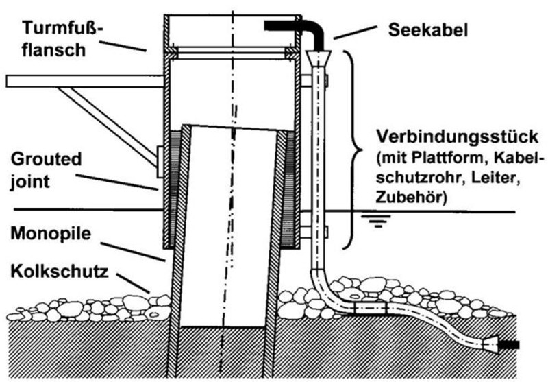
In the offshore oil and gas industry grouted joints belong to the prior art, wherein a transition piece (Transition Piece) is used, which will be charged with a certain overlap length on the monopile. There is thus a tube-in-tube connection, wherein the space between the two tubes is filled with a grout. However, the support structure requires less by normal force, but rather by bending at offshore wind turbines (OWT) as opposed to the oil platforms. Therefore, see the Institute for Steel Construction Leibniz Universität Hannover currently large model tests on grouted joints instead of a pure bending stress.
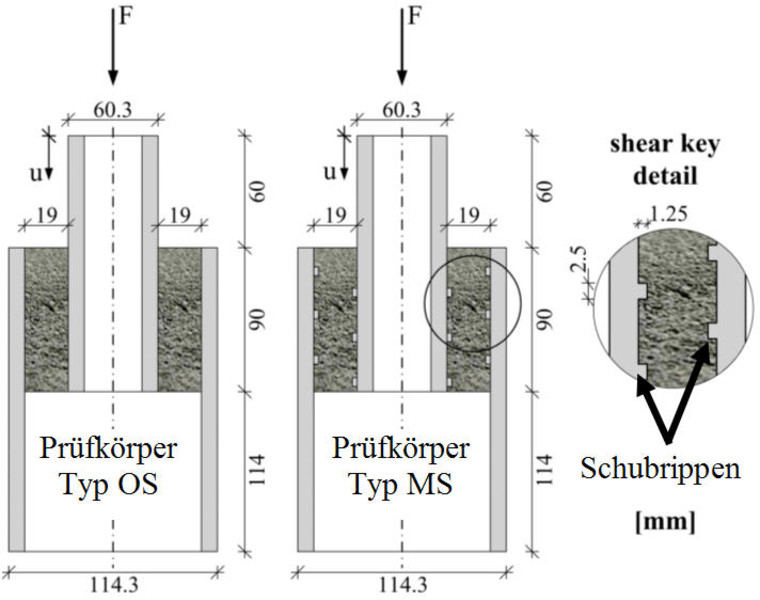
In addition to it already axial pressure tests were performed on small-scale grouted joints, where the focus was on the support and fatigue strength when using different filling materials. In the test program also half of the specimen was equipped with thrust ribs in order to analyze its influence on the ultimate load can. The geometry of the test piece is shown in the figure to the right. More details on this series of experiments are described in the publication Bautechnik Heft 11/2009.
As part of the PhD thesis of Dipl.-Ing. C. Keindorf was developed on the basis of the experimental results, a design proposal for the determination of the load capacity of a grouted joints. The comparison in the following table shows a good agreement between the measurement results and the design proposal.


Comparison between measurement results and design proposal
| Specimens | Compressive strength [MPa] | Load capacity [kN] | Load capacity [kN] |
|---|---|---|---|
| Type | Grout | Test 1 and Test 2 | Design proposal |
| E-MS-T-2 | 87 | 252 and 262 | 287 |
| E-MS-T-3 | 42 | 182 and 192 | 178 |
| E-MS-T-5 | 141 | 437 and 459 | 432 |
Structural behavior with shear ribs
The high load capacity of the test specimens with shear ribs (designation MS) is mainly due to the formation of compression struts in the grouting mortar between the overlapping steel pipes. This load-bearing behaviour therefore differs fundamentally from the test specimens without shear ribs (designation OS). For some grouted joints, the load-bearing capacity and also the fatigue strength could be increased by a factor of 10 by the arrangement of shear ribs.
In addition to the experimental and theoretical investigations in the context found the dissertation of C. Keindorf instead of numerical simulations. Based on the structure of the plot is to see how to train the struts between the shear web. The comparison with the fracture of the specimen shows a good agreement with respect to the mode of action of the load increasing shear web.


Latest posts
Categories

Copyright © 2024
SKI Ingenieurges. mbH
Mengendamm 12
30177 Hannover
Phone: +49 (0) 511 / 261847-0

