Services in the field of welding technology

The SKI engineering company has welding engineers with national and international test certificate. In this case, the following services can be offered in the field of welding technology in the world:

  • Structural analyzes for welds
  • Assessment of the fatigue strength and residual life
  • Individual stages of crack growth in a butt weld
  • Welding simulations
  • Weld after treatments
  • Oscilation tests with a test frequency up to 400Hz
  • External welding supervision and appraisals
External Welding Supervision

The welding engineers of SKI are at your disposal as consultants for your company.

Evaluations
Expertises for welded constructions can be worked on under consideration of various questions. Please contact us in any particular case.
Certificate: International Welding Engineer

Structural analyzes for welds

The evaluation of welded constructions can be done with analytical as well as numerical methods. For standard welding details, which are listed in notch case catalogs, the Nominal stress concept is used often. However, if non-linear stress waveforms are to be assessed in complex welding details, then get local concepts used, e.g. to determine the stress concentration at the weld toe and the weld root. The following figure shows a finite element mesh for both sides welded butt weld to assess the notch stresses at the seam transitions.

FE mesh of a butt weld

Weld after treatments

There are numerous post-treatment processes for welding seams with which different effects can be achieved. In principle, the following effects are possible with the respective processes.

Ground joint test and FE model of a butt weld
Aftertreatment with a high frequency peening methods
MethodReduce the notch effectIntroducing compressive stressesSolidification of the outermost layer
Grinding outyes
TIG meltingyes
Plasma meltingyes
Autofrettageyes
Laserpeeningyes
Shot peeningyesyes
Needles, hammersyesyes
High frequency hammersyesyesyes

Welding simulations

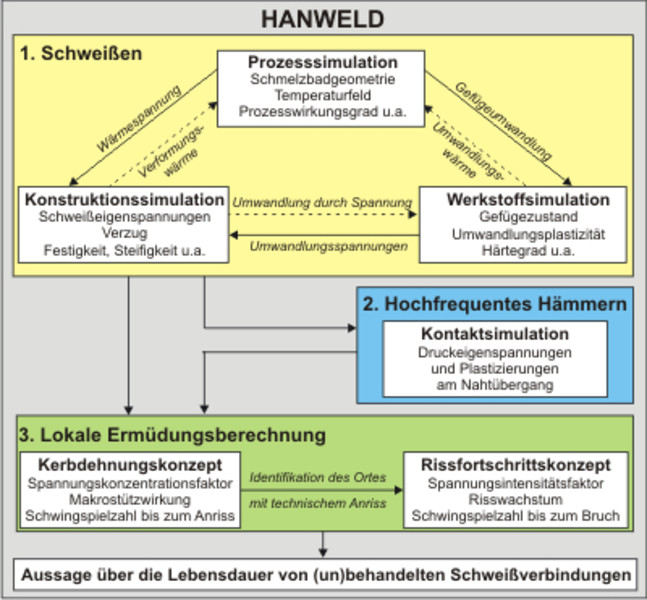
As part of the PhD thesis of Dipl.-Ing. C. Keindorf was developed, the calculation tool HANWELD on the basis of ANSYS ®® simulation package. It includes both the thermal and structural mechanics simulation of a welding process that are additionally coupled kinetics with a module for the structure. The verification of HANWELD was based on welding tests and the welding simulation tool ANSYS. As an example of the multi-level verification, the comparison of temperature cycles is shown in the following figure . 

Following the welding simulation, a hammering process can be carried out as a post weld treatment, which significantly influences the transient residual stress field of the weld seam. 

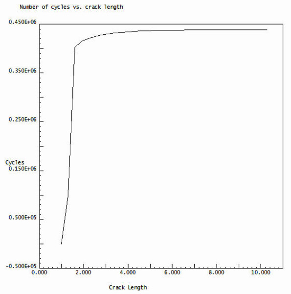
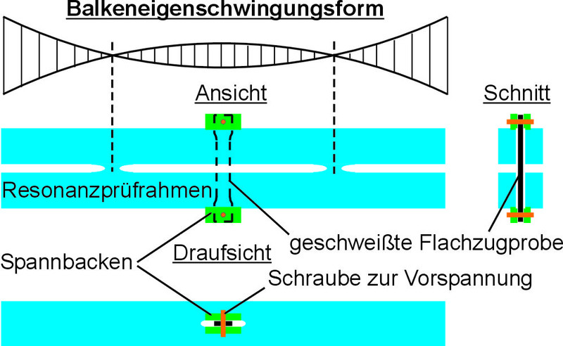
Furthermore, a fatigue module has been integrated into HANWELD, which allows local fatigue calculations to be performed for the welding detail. The respective residual stress conditions of the untreated as well as the post-treated weld seam are taken into account.

Calculation tool HANWELD for welding simulations with integrated fatigue calculations

Thermal analysis of a MAG welding process

Thermal weld seam emulation

Comparison of the temperature cycles between HANWELD / SST / EXPERIMENT

Individual stages of crack growth in a butt weld

Welding details with cracks can be assessed using fracture mechanics methods. Using the example of the butt weld welded on both sides, it is shown how a technical crack progresses at the fatigue-critical seam transition until a residual fracture occurs. The total service life is ultimately determined by the number of cycles of incipient fatigue failure (determined with the notch strain concept KDK) and the number of cycles of failure load (determined with the crack propagation concept RFK).  

The following figures show single Crack stages of 1 mm to 10 mm are shown. In the diagram, the stress intensity factor (SIF) KII on the number of cycles N is evaluated. This means that statements about the remaining service life for steel structures (in this case welding detail) possible. Such inspections can be determined using the crack propagation concept. 

 
Fatigue life as a function of crack propagation
Stress intensity factor as a function of crack propagation
Initial crack a = 1mm
Initial crack a = 3mm
Initial crack a = 7mm
Initial crack a = 10mm

Oscilation tests with a test frequency up to 400Hz

A newly developed magnetic resonance test frame is available for vibration tests on welded joints. This test device uses the first natural oscillation of the arrangement of resonance test frame (RPR) and sample to dynamically load the sample.

The test specimen is preloaded between the opposite sides of a closed frame. A bending natural oscillation of the frame loads the specimen with a harmonic oscillation. The clamping of the specimen in each case in the vibration bulge of the two frame sides results in a pure load in the longitudinal direction of the specimen, i.e. depending on the amount of the preload, an alternating tensile/compressive or pulsating tensile load. The excitation in the form of natural oscillation is carried out electromagnetically by feedback of a strain gauge signal (strain gauge) of the natural oscillation.

The structure is reminiscent of two beams that are elastically connected to each other at two points in such a way that they oscillate in opposite directions in their eigenmodes. From the beam eigenmode of vibration it can be seen that the welded flat tensile specimen is also subject to an oscillation amplitude in the middle. The figure on the right shows the mechanical implementation of the test fixture in the 3D model. It consists of a base plate on which four alternating current magnets and the monolithic RPR are mounted. The electromagnetic vibration excitation is contact-free via the lever arms. The side lengths and cross-sections of the frame were dimensioned in such a way that the RPR can withstand pretensioning forces of 60 KN and test force amplitudes of 50 kN at the same time. The length of the lever arms was determined so that the natural frequency is 400 Hz. 

Further details on the resonance test frame are described below or can be found in a 2008 publication for the Great Welding Conference in Dresden (GST 2008).

Principle of a magnetic resonance test frame
Resonance test frame for welds (Copyright FRAMEWORK)

Test frame details from the magnetic

All necessary components of the test fixture including the control and measurement technology are shown in the figure on the right. A notebook with LabView and measurement card records the measurement data such as preload force, force amplitude, frequency, phase and amplitude of the current at the output of the power amplifier and initiates the abortion of the test as soon as a termination criterion is met. The abort criteria are a manual emergency stop via the keyboard, reaching the number of test load cycles, dropping to a certain preload force and exceeding a tolerance for the actual vaalue of the force amplitude. If one of these criteria is met, the notebook occupies an input of the microcontroller via an output of the measuring card, which then transmits a stop signal to the power amplifier.

Components of the magnetic load frame

Result of Oscillation Test with constant amplitude

In the right figure, the test frequency as a function of the number of cycles is shown on the left ordinate (y-axis). During the transient process this frequency is 388.2 Hz. The right ordinate shows the preload force and the tensile force amplitude as a function of the number of cycles (logarithmic scale). During the transient process the preload force remains constant at 8.6 kN. However, already during the control of the tensile force amplitude, the preload force drops, which indicates a loss of stiffness (crack formation), which continues continuously during the test.

Result of Oscillation Test with variable amplitude

The right figure shows the result of a Oscillation Test is shown with variable amplitude curve. Depending on the number of cycles, the curves for the biasing force, the tensile force and amplitude test frequency are evaluated.
The preload force was adjusted to 8.0 kN before the test. During the subsequent settling of the test frequency initially stood at 386.0 Hz and then fell upon reaching the traction amplitude slightly to 385.8 Hz. As a 100% value for the tensile force amplitude 7.0 kN was chosen, which was maintained for the first 200,000 EV.

Oscillation test with constant amplitude
Oscillation test with variable amplitude

Then the block load simulation was carried out to determine the operational stability, whereby a reduction to 75% and 50% was made for each of the next 200,000 LW. Afterwards the 100% value of the tractive force amplitude was controlled again. Both the test frequency and the preload force remained approximately constant. Finally, an overload was simulated, in which the tensile force amplitude was increased to 125% (8.75 kN). Already when driving this higher amplitude, the preload force dropped continuously, which indicated a progressive loss of stiffness. There was also a slight drop in the test frequency, but this is less suitable as an indicator of the loss of stiffness. The vibration test stopped automatically when the abort criterion for the preload force of 7.5 kN at 1,136,000 LW was reached (total test time only 50 min). At this point in time, the preload force was already well below the tensile force amplitude, resulting in a negative stress ratio of R = -0.08 at the end of the test. Thus, as a further result of the simulation of an overload, it could be shown that this novel resonance test device is also suitable for vibration tests with alternating loads.

Assessment of the fatigue strength and residual life

For dynamically loaded welded structures, a fatigue or durability detection is often required. Basically a sufficient fatigue strength for the respective notch detail against the vibration load has to be detected over the entire lifetime. When SKI engineering company for coming local fatigue concepts apply beyond their performance on the (global) nominal stress concept.

The following is the butt weld shown above on the example, can be done as a fatigue evaluation based on the notch strain concept. In the following figures can be seen as the notch stresses and tolerable numbers of cycles are influenced by a unscheduled offset. In the present case, the lower weld toe is left decisive for the entire fatigue strength of the butt weld. 

Local assessment of the numbers of cycles (fatigue plot)
SKI_Logo_600px_72dpi_rgb

Copyright © 2024 

SKI Ingenieurges. mbH
Mengendamm 12
30177 Hannover

Phone: +49 (0) 511 / 261847-0

Consulting Engineers

BWE Expert Advisory Board