Ring flange connections as an L-or T-variant

Ring flange connections are used in all cases where application tubular sections or components are to be positively connected with each other. They represent an alternative if welded connections are not suitable due to technical or economic criteria. 

For Ring flange connections prestressed bolts are usually used, which have the usual dimensions of M12 to M30 in steel construction.

In the field of wind energy even Bolts are used up to a size of M64 (see size comparison for wolted connections). For example, schedule preloaded Ring flange connections are carried out between the steel tower sections for wind turbines. This Ring flange connections are exposed both in static and in dynamic ways extreme loads. Ring flanges are usually unilateral than with L-shaped flanges, internal cross-section angeordent (see figure at right). In the foot and flanges of T-shaped cross-section are used.

Many other applications for Ring flange connections are in mechanical and plant engineering.

Ring flange connection [SEIDEL, 2001]

Assessment in the ultimate limit state

Evidence of ultimate bearing capacity of Ring flange connections is usually the most highly loaded segment which is cut out of the overall system. This segment approach is illustrated in the figure above. The tensile force in the shell plate of the segment is obtained by integrating the stresses. Advantages are the relatively low computational cost and availability of analytical models. A disadvantage is that the spatial structural behavior can not be mapped.

The viability of the excised segment depends depending on the dimensions of the load capacity of the flange and / or the carrying capacity of the bolt. For the failure of the bolt above all their tension resistance shall prevail.

The calculation of total models is very complicated, but in principle leads to a more economical Assessment, since rearrangement effects can be captured.

FE-model of the ring flange segment
Stress plot for tensile stress
General screw force Traction History [SCHAUMANN et al. 2007]

Assessment in the limit state of fatigue

In the border state of fatigue there is usually an elastic system behavior. The transfer function of the bolt force FS as a function of the tower bending moment MR or the proportionate strength casing plate Z has on the flexural tension side of a nonlinear course on (see figure at right). It is possible to identify four areas:

Range 1: Linear progression, reduction of preload force with fully depressed contact zone

Area 2: Successive gaping of the joint

Area 3: gaping connection ("edge support")

Area 4: Progressive plastification until breakage

In addition to FE-methods, there is a multitude of different analytical methods for the description of the bolt force progression, which is why reference is made to the relevant technical literature at this point.  

Ring flanges and their structural behavior under consideration of imperfections

The SKI Ingenieurges. mbH employs inter alia to with the structural behavior of Ring flange connections, taking into account imperfections. The following failure modes are first to be distinguished:

  • Failure mechanism A: Bolt failure
  • Failure mechanism B: Bolts failure and plastic hinge in the shell plate
  • Failure mechanism C: Plastic hinges in the casing plate and flange

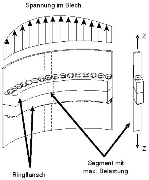
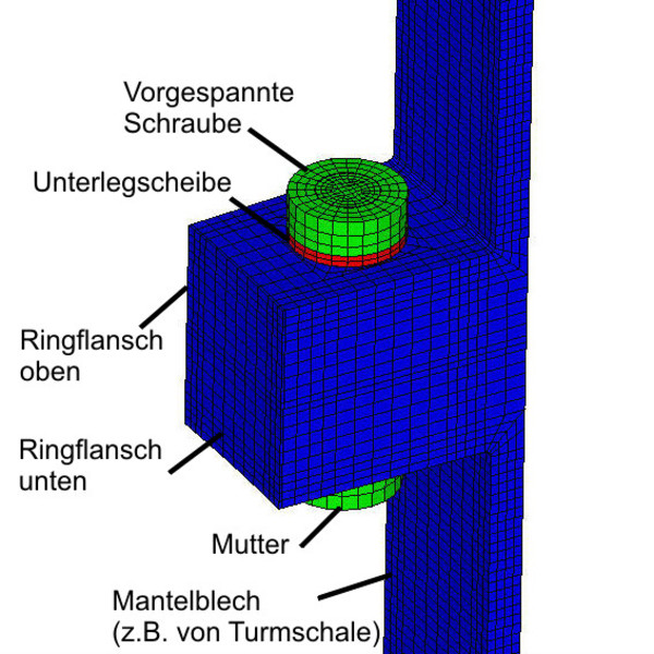
Ring flanges can be analyzed with the help of segment models or even half models, with prestressing forces can be controlled individually each bolt.

Ring flange connection of a steel pipe section

The load-bearing behaviour differs significantly between the bending compression and bending tension side, because flapping can occur under tensile stress. Therefore contact elements were implemented in the FE-model. As a result, the following stresses occur over the circumference. To investigate the influence of imperfections on the load bearing behaviour of RFL, SKI prefers the half model. The main types of imperfections are:

  • Gaping of the flange
  • Gaping tube side
  • Parallel gaping

The FE-model was validated on experimental results obtained in the context of the dissertation by Dr.-Ing. M. Seidel at the Institute of Steel Construction of the Leibniz University of Hanover. The load capacity curves show a very good agreement, see comparison in the diagram between segment model (blue curve) and test results (red curve). The 3rd curve (green) serves as a reference model for another ring flange, which was subsequently examined with a rubber seal. 

Monopile with ring flansch connection

For Offshore wind turbines , Grout connections between Monopile (MP) and Transition Piece (TP) have so far been used to ensure power transmission between the steel pipes. Recent developments show that a ring flange connection with high-strength pretensioned bolts can be used instead of a grout connection, whereby the MP must already be manufactured with an RFL.

The ram energy is applied directly via the ring flange. This process requires a high degree of precession so that the flange of the TP can be attached later on without any problems.

The dynamic laoding caused by the pile-driving process causes high stress amplitudes in the ring flange and the weldseam. In this respect,"pile driving fatigue" must be taken into account when accumulating the operating load collectives in order to be able to make statements about the service lifetime . Imperfections of the ring flange can lead to stress increases in individual sections, so that these influencing variables must also be taken into account when fatigue checks is performed. In this respect, knowledge of the pile driving process as an interaction between hammer, pile and soil on the one hand and the quantitative effects of the parameters on local stress conditions on the other hand are important. SKI's engineers are able to dynamically simulate the pile-driving process and check the corresponding dimensions.

Monopile with ring flange connection at the pile driving

Services

The SKI Ingenieurges. mbH accompanies ring flange connections in the on- and offshore sector with the following range of services:

Copyright © 2024 

SKI Ingenieurges. mbH
Mengendamm 12
30177 Hannover

Phone: +49 (0) 511 / 261847-0

Consulting Engineers

BWE Expert Advisory Board